Aurora Rocketry
Flight software and telemetry for Borealis and Nemesis
Avionics software project manager · Borealis (2024) and Nemesis (2025) · team of 7
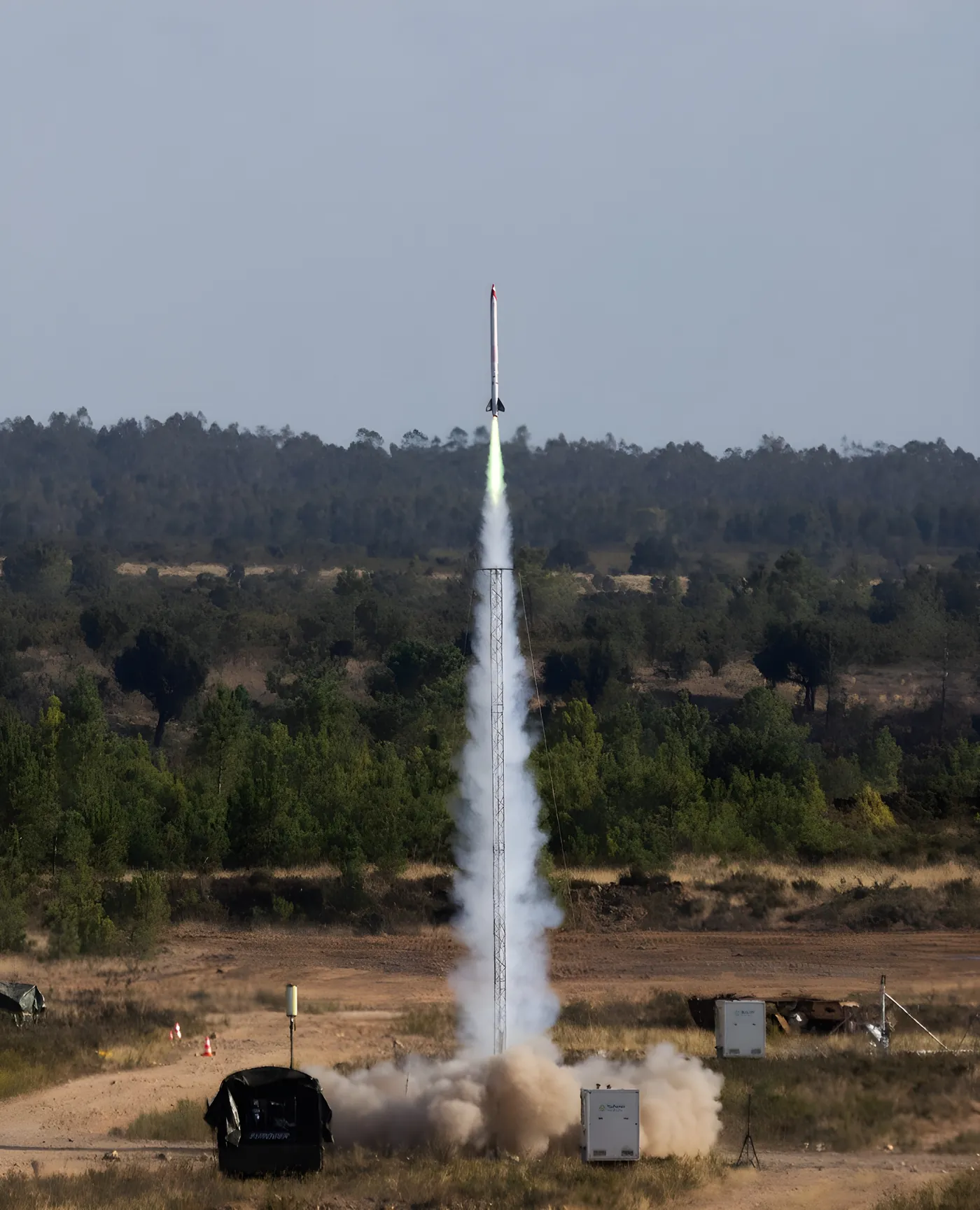
Aurora Rocketry started in 2024. Borealis, our first rocket, was a test vehicle designed to reach 1,500 m. Nemesis followed in 2025: our first competition rocket, built to carry a 1 kg payload to 3,000 m. It launched at EuRoC 2025, the European Rocketry Challenge.
On both I was the project manager of the avionics software, with a team of seven. The flight computer of Borealis and its telemetry are what my bachelor's thesis is about.
Borealis: the flight computer
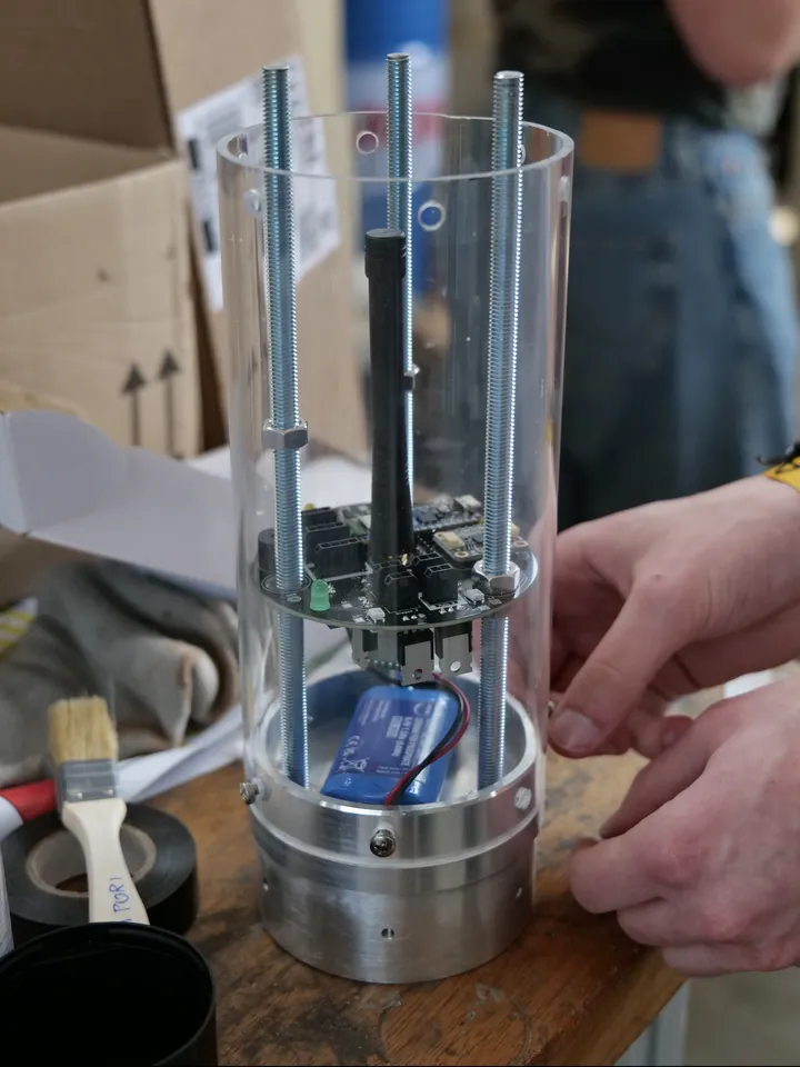
The Borealis flight computer is built around an ESP32-S3 on an Arduino Nano ESP32, on round black boards: a sensor module, and an actuator module that fires the pyrotechnic charges. An Extended Kalman Filter combines the IMU with two barometers on a static port, to estimate orientation, vertical velocity and altitude. The filter corrects the IMU's drift and smooths out the barometers' noise.
When the vertical velocity reaches zero and the rocket starts to fall, it detects apogee and fires the drogue parachute. The main parachute opens at 450 m.
| MCU | ESP32-S3 (Arduino Nano ESP32) |
|---|---|
| IMU | Bosch BNO055 |
| Barometers | 2 × Adafruit MPRLS |
| Fusion | Extended Kalman Filter |
| Radio | EByte E220-900T22D, 868 MHz |
| Recovery | Drogue at apogee, main at 450 m |
Borealis: telemetry
The link is one-way, point to point: an E220 LoRa module on the rocket, another at the ground station on an ESP32-S3 that forwards everything to a laptop. On the ground there's a directional Yagi antenna and no tracking system, so someone has to point it at the rocket by hand.
The rocket body is aluminium, which blocks radio, so the electronics bay sits behind a PMMA window. Flight data goes into a JSON object, gets delta-compressed, split into chunks that fit a LoRa frame, and each chunk gets a small header and a CRC. The ground station puts chunks back in order, rebuilds the message and throws away anything incomplete after a timeout.
In open-field tests the link held beyond 2 km, with an average throughput of about 640 bytes per second. What it couldn't do was recover a lost chunk. Adding that without wasting airtime became LAMP.
Nemesis
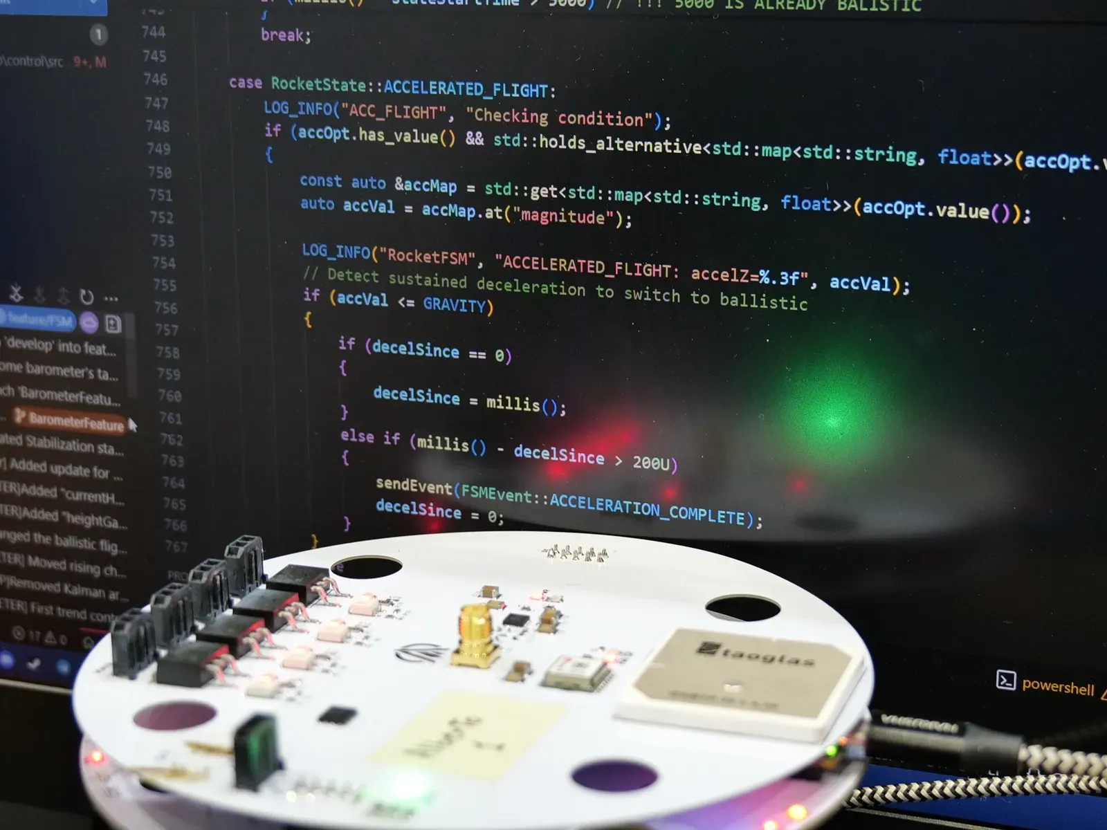
For Nemesis the avionics moved to the round white board in the photo, and the flight software became a state machine with 12 states, from calibration on the pad to recovered on the ground. The code on the screen is the transition out of powered flight: it waits for a sustained drop in acceleration before switching to the ballistic phase. The parachutes fire on entering apogee.
Ground
- 0inactive
- 1calibrating
- 2ground services
- 3ready for launch
Flight
- 4launch
- 5accelerated flight
- 6ballistic flight
- 7apogee
Recovery
- 8stabilization
- 9deceleration
- 10landing
- 11recovered
Nemesis at EuRoC 2025
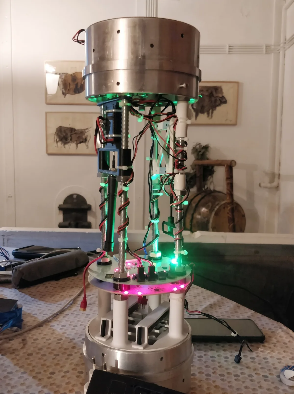
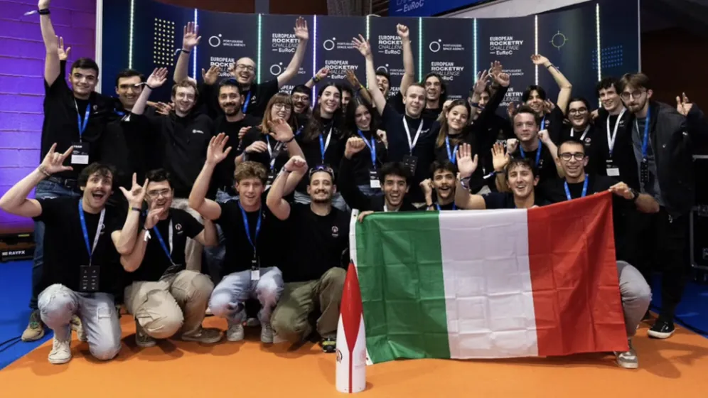
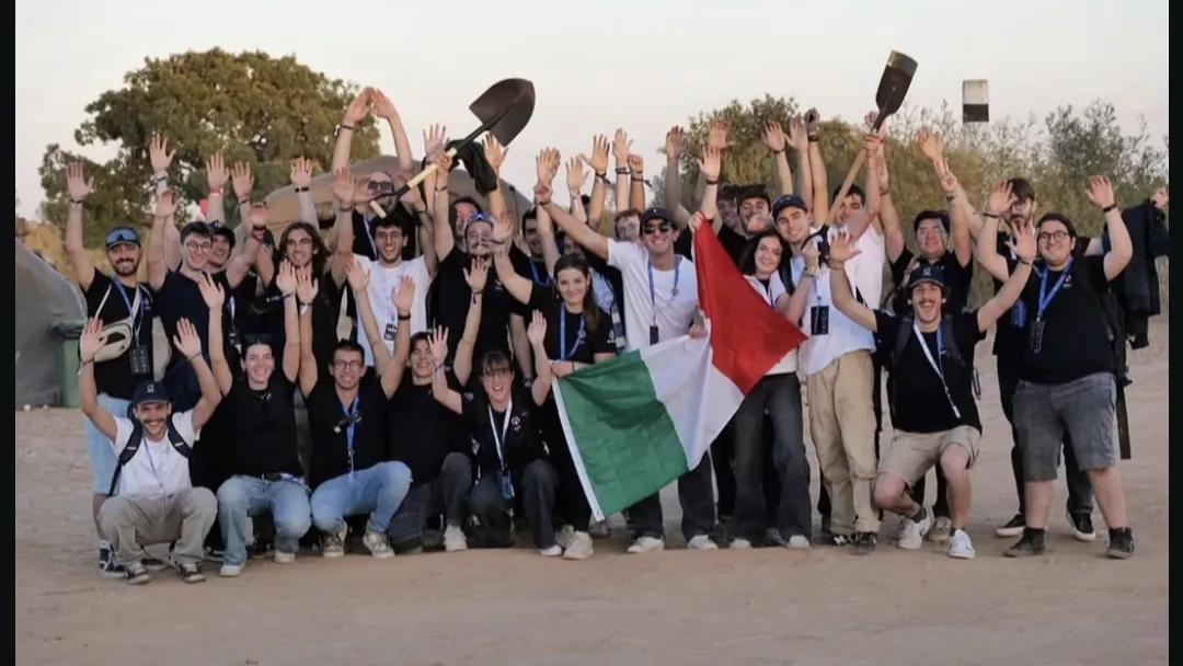
In the electronics bay our board flew next to a second, independent flight computer: a commercial one, based on the Cats Vega. Nemesis launched at EuRoC 2025, and the software for the next rocket refines this one: the base and the states are the same.
Next: LAMP → Bulk data transfer over LoRa