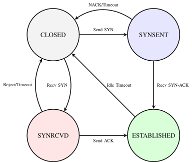
 (a) Connection Session Lifecycle FSM (Stateful vs. Stateless)
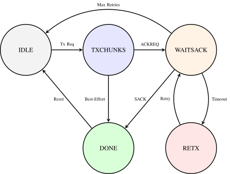 (b) Data Transfer & SACK-ARQ FSM (Reliable vs. Unreliable)
Abstract
This paper presents LoRa Adaptive Multipacket Protocol (LAMP), a lightweight transport architecture that enables the continuous transfer of large data blocks over point-to-point Long-Range (LoRa®) networks. To overcome the prohibitive Time-on-Air overhead and duty-cycle saturation typical of existing Stop-and-Wait solutions, the proposed architecture segments payloads into up to 255 chunks per transmission window. Each chunk is protected by a 9-byte Logical Header with compact 8-bit node addressing (supporting downstream IPv6 link-local prefix mapping) and a 2-byte Cyclic Redundancy Check (CRC)-16 checksum suffix. The protocol provides four distinct operational modes combining connection state (Connectionless / Stateful) and reliability (Best-effort / SACK-ARQ feedback). By requiring receiver feedback only at sequence boundaries rather than per-packet, the Selective Acknowledgment (SACK) mechanism significantly reduces acknowledgment overhead without incurring the constant over-the-air encoding overhead of pure Forward Error Correction (FEC).
Index Terms
Long Range (LoRa), SACK, packet fragmentation, transport protocol, IoT, embedded systems, 3-Way Handshake, point-to-point.
LOW-POWER, low-cost, and long-range wireless communication technologies are becoming increasingly important in the context of the Internet of Things (IoT). Applications such as environmental monitoring, precision agriculture, and autonomous Unmanned Aerial Vehicles (UAVs) require reliable data transmission over extended distances under strict power and hardware constraints [1].
Several communication standards, including ZigBee, Sigfox, and Long Range (LoRa) have been adopted to address these needs, and LoRa, in particular, has emerged as the leading choice for low-power and long-range deployments thanks to its robust modulation technique and open network architecture [2]. However, conventional solutions based on LoRa (particularly those following the Long Range Wide Area Network (LoRaWAN)® specifications) are optimized for small, non-frequent payloads [3].
This limitation poses acute restrictions on data-intensive IoT applications which demand the continuous transfer of large data blocks [4, 5], such as Firmware Update Over The Air (FUOTA), Simultaneous Localization and Mapping (SLAM) map transfers in autonomous robotics, or bulk sensor log collection. Standard LoRaWAN links require substantial transmission overhead, restrictive duty-cycle limitations [6], and lack optimized mechanisms for handling large, multi-packet payloads in point-to-point configurations.
This paper presents the design and implementation of LoRa Adaptive Multipacket Protocol (LAMP), a lightweight transport protocol for point-to-point and local multi-node LoRa networks. LAMP supports payloads up to 62.2 kB on 255 byte First-In, First-Out (FIFO) transceivers (such as the Semtech® SX1262), operating independently of higher-layer middleware such as LoRaWAN.
The main contributions of this work are:
The remainder of this paper is organized as follows. Section II surveys related work and defines the design space. Section III details the system architecture, packet structure, and formal protocol mechanisms. Section III-F presents the hardware-level C++17 implementation. Section IV evaluates performance through extensive ns-3 simulations, validates the firmware functionally on hardware with emulated frame loss, and frames the outdoor field campaign as planned future work. Section V concludes the paper and presents the architectural roadmap. Extended driver bindings, formal state machines, and secondary simulation blocks (F, G, H) are provided in the companion Supplementary Material.
Reliable packet fragmentation and transport over Low-Power Wide-Area Networks (LPWANs) has been the subject of extensive investigation, driven by the expanding demand for data-intensive IoT workloads [4, 5]. Existing approaches broadly fall into three categories: standardized LPWAN frameworks, conventional Stop-and-Wait ARQ, and specialized windowed batch transports.
At the standardization level, the IETF defined Static Context Header Compression (SCHC) [9, 7], introducing a generic architecture for header compression and fragmentation over LPWANs. RFC 9011 defines SCHC profiles over LoRaWAN supporting No-ACK, ACK-Always, and ACK-on-Error modes. While SCHC achieves high compression for predictable IPv6/UDP flows (down to 1–2 bytes), it relies on pre-provisioned static rule contexts and gateway-centric infrastructure, making it ill-suited for autonomous, ad-hoc raw-LoRa peer-to-peer or multi-node links. Similarly, the LoRa Alliance standardized Fragmented Data Block Transport Specification (TS004) [10] to support FUOTA via open-loop Forward Error Correction (FEC) redundancy codes. While open-loop FEC delivers multicast firmware images without requiring a reverse feedback channel, it introduces continuous over-the-air encoding overhead regardless of physical channel conditions and imposes substantial computational decoding demands on resource-constrained microcontrollers.
Bitmap-based selective feedback is not new in this space: SCHC’s ACK-on-Error mode returns a compressed bitmap of the tiles received in a window [7], and 6LoWPAN Selective Fragment Recovery confirms fragments through a 32-bit acknowledgment bitmap [11]. LAMP adopts the same principle but applies it end-to-end over raw LoRa links, without rule contexts or IP infrastructure, with a single uncompressed bitmap covering up to 255 chunks.
In infrastructure-free point-to-point and local mesh configurations, early implementations relied on S&W Automatic Repeat Request (ARQ). However, empirical link evaluations by Cattani et al. [12] and network scalability analyses by Bor et al. [13] established that per-fragment acknowledgments incur prohibitive Time-on-Air latencies and severe duty-cycle saturation when applied to multi-packet payloads. Under typical LPWAN channels, the round-trip overhead of waiting for an individual ACK after every single packet dramatically reduces effective throughput.
Open-source LoRa libraries follow the same pattern. RadioHead offers an 8-bit TO/FROM/ID/FLAGS header with broadcast address 255 and a reliable datagram layer with per-message acknowledgments, timed retransmissions and duplicate detection, which blocks the sender until each message is acknowledged [14]. The large-transfer service built into LoRaMesher [15, 16] applies stop-and-wait ARQ with a SYNC handshake, per-chunk acknowledgments, receiver-side requests for lost packets and RTT-based timeouts, and was evaluated on ten real nodes in two topologies. LAMP differs in using one cumulative bitmap per repair round and in offering four operational modes. Section IV-A compares LAMP with MPLR and with this service in simulation.
To mitigate Stop-and-Wait overhead, Chen et al. [8] proposed Multi-Packet LoRa (MPLR), introducing windowed batch transmissions acknowledged by a bit-vector acknowledgment packet (BVACK). While pioneering bitmap feedback over LoRa, MPLR was engineered as an application-specific image uplink pipeline with key architectural constraints: a 16-byte fixed header (allocating 4 bytes each to source and destination Extended Unique Identifiers (EUIs)), rigid single-mode stateful batching (up to 40 packets), and an explicit 4-way teardown sequence (FIN/ACK) without run-time buffer negotiation.
LAMP addresses these gaps by establishing an autonomous, lightweight transport layer operating directly over raw LoRa PHY. As summarized in Table I, LAMP advances the state of the art through four core design principles: (i) a compact 9-byte Logical Header (11 bytes over the air with CRC-16), reducing control overhead by 31.2% compared to MPLR; (ii) four configurable operational modes spanning connectionless and stateful best-effort and SACK-ARQ transfers; (iii) dynamic buffer safety via run-time 3-Way Handshake (3WHS) parameter negotiation (SynMetadata) with automatic inactivity pruning; and (iv) a pure C++17 core isolated from physical transceivers via an extensible HAL.
| Architectural Dimension | SCHC [9] | LoRaWAN TS004 [10] | MPLR [8] | Proposed (LAMP) |
|
| Stack Dependency | Raw LoRa PHY | Generic Adaptation (often LoRaWAN/IP) | LoRaWAN App Layer | Raw LoRa PHY | Raw LoRa PHY (Standalone) |
| ACK Mechanism | Per-Packet ACK | Compressed bitmap (ACK-on-Error) / ACK-Always | None (Open-Loop Redundancy) | Bit-Vector SACK | Bit-Vector SACK |
| Header Overhead | 4 Bytes (RadioHead), 11 Bytes (LoRaMesher) | 1–2 Bytes (Compressed RuleID/Residue) | 2 Bytes | 16 Bytes | 9 Bytes (11B total w/ CRC) |
| Max Frame Payload | 251 Bytes (RadioHead), 211 Bytes (LoRaMesher) | Variable | Variable | 239 Bytes | 244 Bytes (255B PHY limit) |
| Max Session Payload | Unbounded (Sequential) | Variable (IPv6 Packet) | Unlimited (Block Session) | Multi-MB Image (65k Packets) | 62.2 kB (255 Chunks / Session) |
| Operational Modes | 1 (Reliable S&W) | 3 (No-ACK, ACK-Always, ACK-on-Error) | 1 (Open-Loop FEC) | 1 (Reliable Batch) | 4 Configurable Modes |
| Node Addressing | None / Application | IPv6 128-bit (Compressed) | DevAddr (32-bit) | EUI (32-bit) | 8-bit Unicast + Broadcast |
| Multi-Node Suitability | Single P2P Link | Star (Gateway-Centric) | Star Broadcast (Downlink) | Node–GW uplink (star, 5–20 nodes tested) | P2P & Multi-Node Ready |
| Parameter Negotiation | None (Static) | Static (Pre-shared Rules) | Static / Out-of-Band | Static Batch / 4WHS | Dynamic 3WHS Metadata |
| Key Strengths | Minimal header size, trivial implementation | Header compression (1–2 B) for IP traffic | No feedback channel required (pure FEC) | High-volume image uplink batching | 4 flexible modes, dynamic 3WHS buffer safety, raw LoRa autonomy |
| Key Limitations & Trade-offs | Prohibitive airtime latency, duty-cycle saturation; 20 s minimum timeout (LoRaMesher) | Requires shared rule context & IP infrastructure | High FEC compute cost, constant airtime overhead | 16B header overhead, single mode, 4WHS teardown | 9B header (11B w/ CRC), 62.2 kB session limit, RAM/timer state |
LAMP is a transport-layer protocol running directly over raw LoRa transceivers (such as the Semtech SX1262), segmenting payloads up to 62.2 kB into chunks of up to \(S_{\max } = 244\) bytes while minimizing Logical Header and Over-the-Air (OTA) overhead.
Extending an earlier unaddressed prototype, the production architecture employs a compact 9-byte Logical Header (11 bytes over the air including a 2-byte Modbus CRC-16 suffix, polynomial 0xA001), shown in Fig. 1. Adding 8-bit addressing (srcAddr, dstAddr) increases frame length by \(<0.8\%\) at maximum frame size (255 B) while enabling session isolation, dynamic buffer negotiation, and direct mapping to IPv6 link-local addresses at edge gateways.
To accommodate diverse IoT workloads, LAMP defines four operational modes (Table II) across Reliability (Best-Effort vs. SACK-ARQ) and Connection State (Connectionless vs. Stateful).
| Mode | State / ARQ | Target Application |
| Mode 1 | Connectionless / Best-Effort | Periodic telemetry, broadcast bursts |
| Mode 2 | Stateful / Best-Effort | Session-tracked real-time streams |
| Mode 3 | Connectionless / SACK | High-priority isolated bursts |
| Mode 4 | Stateful / SACK | Bulk payloads (FUOTA, maps) |
Start-of-Message (SOM) and End-of-Message (EOM) boundaries are derived implicitly: \(\mathrm {SOM} \iff \texttt {chunkIndex} == 0\) and \(\mathrm {EOM} \iff \texttt {chunkIndex} == \texttt {totalChunks} - 1\). Carrying totalChunks in every chunk enables receivers to pre-allocate reassembly buffers and SACK bitmaps upon receiving any fragment, even out of order.
The 8-bit Node ID space spans 0x00 (unassigned), 0x01–0xFE (254 unicast nodes), and 0xFF (broadcast, restricted strictly to Mode 1 to avoid ACK implosion). Active and completed sessions are uniquely keyed by \((\mathtt {srcAddr}, \mathtt {messageId})\). The receiver retains the last \(\texttt {MAX\_COMPLETED\_HISTORY} = 16\) completed message IDs for at least 120 s (and \(1.2\times (R_{\mathrm {max}}+1)\) SACK timeouts, \(\approx 100\) s at SF12/125 kHz) so that duplicate trailing chunks trigger a terminal SACK without duplicate application delivery; history for a sender is flushed when a valid SYN arrives, and the initial message ID is drawn randomly (never 0) to prevent collisions after reboot.
| Byte 0 | Byte 1 | Bytes 2–3 | Byte 4 | Byte 5 | Byte 6 | Byte 7 | Byte 8 |
| srcAddr | dstAddr | messageId | totalChunks | chunkIndex | payloadSize | flags | protocolVersion |
The fields in Fig. 1 specify: source and destination node IDs (srcAddr, dstAddr); a 16-bit messageId; payload fragmentation bounds (\(1 \le \texttt {totalChunks} \le 255\), \(0 \le \texttt {chunkIndex} < \texttt {totalChunks}\)); application payload length (\(0 \le \texttt {payloadSize} \le 244\) B, yielding \(255 \times 244 = 62,220\) B \(\approx 62.2\) kB maximum session capacity); a 1-byte control flags bitfield; and protocolVersion (set to 2). The 2-byte CRC-16 suffix is computed over the 9-byte header and exactly payloadSize bytes, omitting trailing buffer padding.
Table III summarises all defined flag combinations and the behaviour of the packet parser upon receipt of an undefined value.
| Value | Semantic | Notes |
| 0x00 | Data chunk | Unreliable/reliable chunk, no ACK |
| 0x04 | Final chunk (ACK_REQ) | Receiver replies with SACK |
| 0x08 | SACK feedback | Payload = received-chunk bitmap |
| 0x10 | SYN | 3WHS Step 1 (SynMetadata) |
| 0x30 | SYN-ACK | 3WHS Step 2 (SynAckMetadata) |
| 0x20 | ACK | 3WHS Step 3, no payload (\(L=0\)) |
| 0x40 | CONN-NACK | Payload = rejection reason code |
| other | Undefined | Silently discarded |
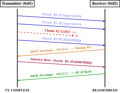
In reliable modes (Modes 3 and 4), LAMP implements a SACK mechanism [17, 18] to recover lost fragments with minimal airtime. The sender streams chunks sequentially, asserting FLAG_ACK_REQ on the final chunk. The receiver returns a SACK frame (FLAG_ACK) carrying an uncompressed bitmask of received chunks (\(\lceil N/8 \rceil \) bytes, LSB-first). The transmitter selectively retransmits only missing chunks with FLAG_ACK_REQ on the last repair frame, iterating until complete or the repair budget \(R_{\mathrm {max}} = 5\) is exhausted.
If a SACK is not received within the dynamic timeout window, the sender re-transmits the chunk carrying FLAG_ACK_REQ from the preceding round, repairing lost query chunks while prompting feedback. Timeouts and repair rounds share the common budget of \(R_{\mathrm {max}} = 5\). The timeout is computed adaptively: \begin{equation} T_{\mathrm {timeout}} = \max \!\left (T_{\min },\;\alpha \cdot \left (\widehat {T}_{\mathrm {oA, DATA}} + \widehat {T}_{\mathrm {oA, SACK}}\right ) + \delta \right ) \label {eq:timeout} \end{equation} where \(T_{\min } = 1000\) ms, \(\alpha = 1.5\), \(\widehat {T}_{\mathrm {oA, DATA}}\) and \(\widehat {T}_{\mathrm {oA, SACK}}\) are Times-on-Air queried from the radio driver [19], and \(\delta = 50\) ms accounts for transceiver half-duplex turnaround (\(\delta _{\mathrm {sw}} = 25\) ms) and RTOS scheduling jitter (25 ms), yielding \(T_{\mathrm {timeout}} = 1000\) ms at SF7 and 3927 ms at SF10 for \(N=20\) (Supplementary Table S-I). Under independent frame loss probability \(p\) and error-free control feedback, the burst delivery success probability across \(R_{\mathrm {max}}\) retries is bounded by \(P_{\mathrm {success}} \le \left (1 - p^{R_{\mathrm {max}} + 1}\right )^N\) (\(P_{\mathrm {fail}} = 1 - P_{\mathrm {success}}\)), yielding \(P_{\mathrm {success}} \le 99.87\%\) for \(N=20\), \(p=0.20\), and \(R_{\mathrm {max}}=5\) (99.0% in Monte Carlo simulations).
To ensure memory safety on embedded targets, receiver memory for an incomplete session is bounded by \(M_{\mathrm {session}} = N\,(S_{\mathrm {pkt}} + S_{\mathrm {node}})\), where \(S_{\mathrm {pkt}} = 255\) B (chunk buffer) and \(S_{\mathrm {node}} \approx 32\) B (container overhead); metadata (\(\approx 48\) B) and bitmask (\(\lceil N/8 \rceil \) B) are below 1%. Reconstruction allocates the \(N\,S_{\max }\) output buffer (\(S_{\max } = 244\) B), peaking at \(N\,(S_{\mathrm {pkt}} + S_{\mathrm {node}} + S_{\max })\). For \(N=20\) (4.88 kB), \(M_{\mathrm {session}} = 5.74\) kB during transfer and 10.6 kB at reconstruction. With \(\texttt {MAX\_CONCURRENT\_SESSIONS} = 10\), ten active sessions plus one reconstruction hold \(\approx 62\) kB (\(\approx 12\%\) of ESP32-S3 SRAM). Admission control rejects incoming sessions if slots saturate or free heap drops below a 16 kB margin.
(a) Connection Session Lifecycle FSM (Stateful vs. Stateless)
(b) Data Transfer & SACK-ARQ FSM (Reliable vs. Unreliable)
To support stateful stream negotiation and protect resource-constrained receivers from buffer overflows, LAMP introduces a 3WHS mechanism. Fig. 2 summarizes the session and data-transfer state machines, while Fig. 3 illustrates the corresponding sequence flows.
The connection lifecycle follows a three-step exchange (Fig. 3(a)):
Once established, data streaming proceeds as in Fig. 4. Five deterministic fault-handling rules ensure multi-node stability: (i) Simultaneous Connection Resolution: The node with the higher numerical address yields and treats the incoming SYN as an inbound request, while the lower address responds with CONN_NACK(BUSY) (Fig. 3(b)); (ii) Implicit Promotion: If the final ACK is lost, the responder transitions to ESTABLISHED upon receiving the peer’s first data frame; (iii) Admission Limits: Receivers reject SYN requests with CONN_NACK(BUSY) when session tables saturate, free heap drops below 16 kB, or a stateful link is already active; (iv) Address Filtering: Frames from unexpected nodes are discarded; and (v) Handshake Timeout: Lost handshakes abort to CLOSED. Formal algorithmic pseudo-code for receiver reassembly and transmitter SACK-ARQ streaming is provided in Algorithms S-1 and S-2 of the Supplementary Material.
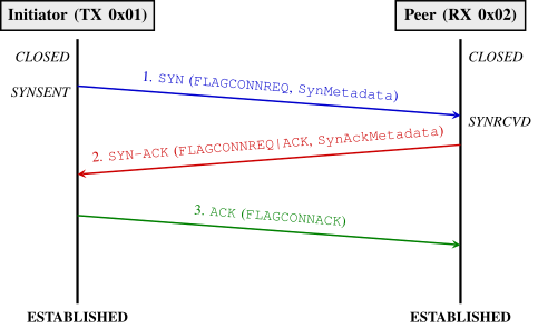 (a) Successful 3-Way Handshake (3WHS) with Metadata Negotiation
 (b) Connection Rejection (CONN_NACK) Failure Mode
The LAMP protocol is implemented as a production C++17 library decoupled via a Hardware Abstraction Layer (IRadio, IPlatform), interfacing an ESP32-S3 microcontroller to a Semtech SX1262 transceiver via SPI and interrupt GPIOs (EspHal). Operational limits (\(R_{\mathrm {max}} = 5\), \(\texttt {MAX\_CONCURRENT\_SESSIONS} = 10\), \(\texttt {PHY\_BUFFER\_SIZE} = 256\) B) reside in a centralized configuration namespace (LoRaMultiPacketConfig). The state machine was verified across 72 host unit tests in PlatformIO. The hardware bench comprises two Heltec Wi-Fi LoRa 32 V3 nodes (869.525 MHz, \(BW = 125\) kHz, CR 4/5, +10 dBm) under the ETSI EN 300 220-2 10% duty-cycle envelope (Band P). Extended driver bindings and FreeRTOS task mappings are documented in Section S-II of the Supplementary Material.
To evaluate the reliability, throughput, and communication limits of LAMP, we adopt a three-part methodology: a large-scale stochastic simulation campaign executed in ns-3; a functional validation of the firmware on two microcontroller nodes with emulated frame loss, compared run-by-run against the simulator; and a planned outdoor field campaign, which is future work. The simulation results characterize the protocol under published channel models, the bench shows that the firmware behaves as the simulator does, and neither measures propagation on real links.
To characterize protocol performance under controlled fading channels, we developed a C++ simulator integrated into the ns-3 framework (version 3.48, development snapshot of 2 June 2026) and the lorawan module (one commit after release v0.3.7, 67bcaef). The simulator reproduces the LAMPv2 frame (9-byte Logical Header carried as a real packet header, plus the 2-byte CRC-16), all four operational modes, the 3WHS handshake and selective bit-vector SACK retransmissions: the receiver returns the bitmap of the chunks it actually holds and the transmitter re-sends only the missing ones. Timers and the repair budget \(R_{\mathrm {max}}=5\) mirror ProtocolConfig.hpp. As a baseline it implements Stop-and-Wait ARQ (one acknowledgment per frame, up to \(R_{\mathrm {max}}\) retries per chunk) with two timeouts: the rule of Eq. (1) (“base”) and a tight timeout of one acknowledgment airtime plus 50 ms (“tight”). Two related protocols run on the same PHY, channel and seeds. MPLR [8] is modelled with its 16-byte header (239 B of data per frame, no additional CRC), batches of up to 40 frames acknowledged by one bit-vector packet, a SYN/SYN-ACK handshake and a FIN/ACK/FIN/ACK teardown; its article specifies neither timers nor retry limits, so we reuse the SACK timeout rule of LAMP and \(R_{\mathrm {max}}=5\). The LoRaMesher large-transfer service [16] is modelled as stop-and-wait with an 11-byte header (211 B of data), a SYNC/ACK handshake, one acknowledgment per chunk, up to 10 consecutive timeouts and a 20 s minimum timeout; we also run it with the tight timeout above and with 5 retries, the budget of LAMP. Its receiver-side requests for lost packets are not modelled. All protocols carry the same 4.88 kB message, in 20 (LAMP), 21 (MPLR) and 24 (LoRaMesher) data frames.
The channel combines a single-slope log-distance path loss, a log-normal shadowing offset drawn once per transfer and Nakagami-\(m\) fast fading, with a transmit power of +24.2 dBm Effective Isotropic Radiated Power (EIRP) (22 dBm PA, 3 dBi antenna, 0.8 dB connector loss) and a receiver noise floor of \(-174\,\mathrm {dBm/Hz} + 10\log _{10}BW + 6\) dB. Table IV lists the parameters, from the Line-of-Sight (LoS) free-space case to the Urban-like stress channel. The Urban and Water scenarios are the fits of Petäjäjärvi et al. [20] (868.67 MHz, car on the ground and boat on the water, SF12 data); other measured urban exponents range from 1.58 [21] to 2.71 [5]. The Rural scenario is the re-fit of measurements by Chall et al. published in the review [22], not a value from the original article. The Nakagami shape factors (\(m=3\), 1.5, 1) are modelling assumptions for which we found no LoRa measurement. Two stress channels reuse earlier, steeper parameters (\(n=4.0\) and \(n=4.5\)) as explicit worst cases.
| Scenario | \(\boldsymbol {n}\) | PL (dB) | \(\boldsymbol {\sigma }\) (dB) | \(\boldsymbol {m}\) | Source |
| LoS (free space) | 2.00 | 91.2 | 0 | 3 | free space |
| Urban | 2.32 | 128.95 | 7.8 | 1 | [20] |
| Rural | 2.93 | 110.0 | 6.3 | 1.5 | re-fit in [22] |
| Water | 1.76 | 126.43 | 8.0 | 3 | [20] |
| Stress (LoS-like) | 4.0 | 113 | 0 | 3 | worst case |
| Stress (Urban-like) | 4.5 | 131 | 0 | 1 | worst case |
Reception in ns-3 is decided by comparing the received power with a per-SF sensitivity threshold. The thresholds of the simulator correspond to SNR values about 5 dB lower than the SX1262 datasheet figures (\(-7.5\) dB at SF7, \(-15\) dB at SF10). Absolute ranges are therefore optimistic by that margin, and the main results are reported against nominal SNR; calibrating the threshold on real links is left to the field campaign.
The campaign comprises 295,800 independent runs (50 seeds per point, \(N=20\) chunks of 244 B = 4.88 kB): Block A (37.2k runs, static AWGN sweep \(-25\) to \(+5\) dB), Block B (71.4k runs, channels of Table IV), Block C (2.8k runs, hardware bench model), Blocks D and E (108.6k runs, MPLR and LoRaMesher benchmarks on paired seeds), and secondary Blocks F–H (75.8k runs, message scaling to 62.2 kB, ACK loss, and timer ablation, detailed in Supplementary Material).
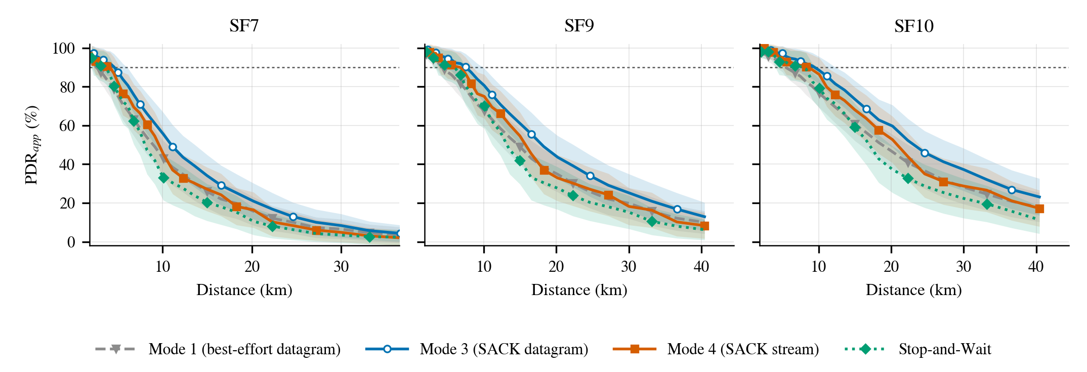
\(PDR_{\mathrm {app}}\) is the number of distinct chunks received divided by \(N\). Goodput is the delivered application bits divided by transfer time \(T\) (completion time for acknowledged modes, arrival of last chunk for best-effort). Sustained goodput under the 10% duty cycle replaces \(T\) by \(\max (T, T_{\mathrm {air}}/0.10)\), where \(T_{\mathrm {air}}\) is sender airtime. Crucially, when reliable modes (Modes 3 and 4) achieve 100% \(PDR_{\mathrm {app}}\) in Fig. 5, this indicates successful SACK-ARQ recovery within the \(R_{\mathrm {max}} = 5\) budget rather than zero physical loss on the channel.
In the static AWGN channel (detailed with full curves in Section S-IV and Fig. S-8 of the companion Supplementary Material), above the reception threshold every mode delivers the full payload; the threshold lies at about \(-12\) dB (SF7), \(-17\) dB (SF9) and \(-20\) dB (SF10), and the transition takes only 2–3 dB. In a static channel the benefit of selective repair is therefore confined to a narrow band (the 50% point of Mode 3 is about 1 dB below that of Mode 1 at SF7); fading widens the transition and the benefit grows.
In the lossless region the SF7 goodput is 4.83 kbit/s for Mode 1, 4.78 for Mode 3, 4.70 for Mode 4 and 4.14 kbit/s for Stop-and-Wait, so the SACK modes are 14–16% faster than Stop-and-Wait at SF7 (and 11–13% at SF9 and SF10). Mode 4 is about 2% slower than Mode 3 because of the handshake. Under the 10% duty cycle the sustained goodput is airtime-bound at about 488, 156 and 85 bit/s for SF7, SF9 and SF10 respectively for every mode (484 and 84 bit/s for Mode 4 at SF7 and SF10): the choice of mode does not change the sustained rate, only the duration of a single transfer and its reliability under fading.
Table V reports the largest distance at which the mean \(PDR_{\mathrm {app}}\) over 50 seeds (each with its own shadowing draw, identical across modes, so that modes are compared on paired seeds) stays at or above 90%, and Fig. 5 shows the Urban curves. In urban propagation at SF7, Mode 3 reaches 4.6 km and Mode 4 4.1 km, against 3.4 km for Stop-and-Wait and 2.5 km without reliability (Mode 1). The gain of Mode 3 over Stop-and-Wait is 22–35% for the Urban channel, 14% for Water and 8–17% for Rural. Stop-and-Wait needs an acknowledgment for every chunk, and every lost acknowledgment consumes a retry, whereas LAMP asks for one SACK per burst. Mode 4 trails Mode 3 because the handshake must also succeed. With a 1 dB SNR grid, one grid step corresponds to 8–14% in distance, so differences of that size (e.g. Rural at SF7 and SF9) should not be over-interpreted. The ordering is unchanged in the stress channels: Mode 4 reaches 9.6 km (SF7) against 9.0 km for Stop-and-Wait in the LoS-like channel, and 2.7 against 2.5 km in the Urban-like channel.
| Channel | SF | Mode 1 | Mode 3 | Mode 4 | S&W |
| Urban | 7 | 2.51 | 4.56 | 4.13 | 3.38 |
| Urban | 9 | 4.13 | 7.48 | 6.78 | 5.56 |
| Urban | 10 | 5.03 | 9.13 | 8.27 | 7.48 |
| Rural | 7 | 12.55 | 15.89 | 14.69 | 14.69 |
| Rural | 9 | 18.59 | 23.53 | 21.76 | 21.76 |
| Rural | 10 | 23.53 | 29.79 | 27.54 | 25.46 |
| Water | 7 | 7.90 | 10.27 | 9.01 | 9.01 |
| Water | 9 | 15.20 | 19.75 | 17.33 | 17.33 |
| Water | 10 | 22.51 | 29.24 | 25.65 | 25.65 |
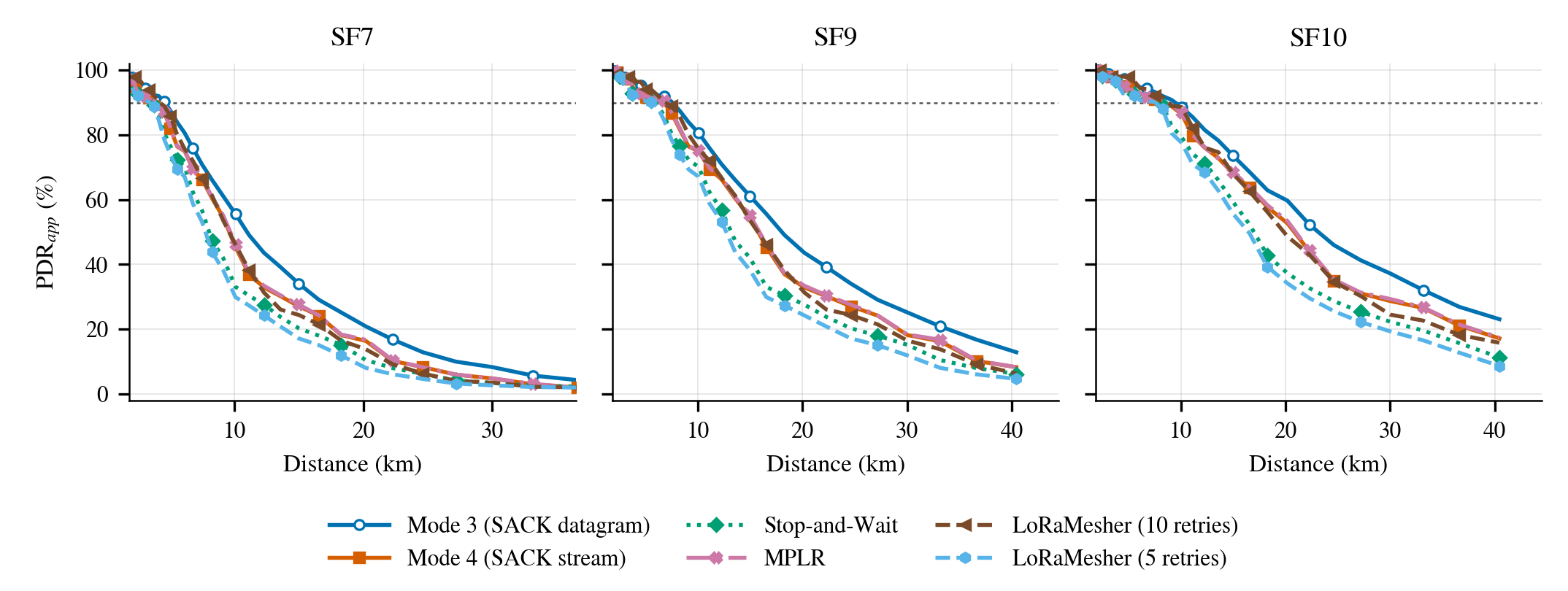
Table VI compares LAMP with the two related protocols at SF7; Fig. 6 shows the Urban channel, while Rural, Water, and Static AWGN channel curves are reported in Section S-IV and Figs. S-5–S-8 of the companion Supplementary Material. SF9 and SF10 yield identical relative performance ordering. In the static channel all acknowledged protocols reach 90% at the same SNR (\(-12\), \(-17\) and \(-20\) dB at SF7, SF9 and SF10): the differences appear after the threshold, and with fading.
In the lossless region the compact header and the single-bitmap exchange make LAMP the fastest. At SF7 Mode 3 sustains 4.78 kbit/s against 4.48 for MPLR (+7%) and 3.92 for LoRaMesher (+22%), and delivers the message in 8.2 s against 8.7 and 10.0 s; Mode 4, which pays the handshake, is still 5% above MPLR. Under the 10% duty cycle the sustained rates are 488, 468 and 480 bit/s, a gap of 4% and 2%, because that rate is airtime-bound.
In faded channels, MPLR matches Mode 4 range across all nine channel/SF cases (Table V), as \(N=20\) fits one MPLR batch (handshake plus one bit-vector round). Mode 3 reaches 8–14% farther by avoiding handshake overhead. LoRaMesher’s reach depends on its retry budget: with 10 timeouts per chunk it matches Mode 4 (Urban/Rural) and Mode 3 (Water), but with LAMP’s 5-retry budget it falls to Stop-and-Wait levels (3.4, 14.7, 9.0 km at SF7). Crucially, this extended reach incurs severe latency: at 4.1 km in Urban SF7, mean sender time is 191 s (20 s minimum timeout) versus 11 s for Mode 3. These baselines reflect reimplementations under identical PHY and channel models.
| Protocol | Frames | bit/s | s | Urban | Rural | Water |
| Mode 3 | 20 | 4784 | 8.2 | 4.56 | 15.89 | 10.27 |
| Mode 4 | 20 | 4702 | 8.3 | 4.13 | 14.69 | 9.01 |
| S&W | 20 | 4138 | 9.4 | 3.38 | 14.69 | 9.01 |
| MPLR | 21 | 4475 | 8.7 | 4.13 | 14.69 | 9.01 |
| LoRaMesher (\(R=10\)) | 24 | 3919 | 10.0 | 4.13 | 14.69 | 10.27 |
| LoRaMesher (\(R=5\)) | 24 | 3919 | 10.0 | 3.38 | 14.69 | 9.01 |
Extended parametric evaluations are detailed in Section S-IV of the companion Supplementary Material: (i) Message Scaling (Block F): evaluating transfers up to 62.2 kB (\(N=255\) chunks) proves that LAMP’s delivery range remains invariant to payload size (Mode 4 maintains 4.13 km in urban channels), whereas per-chunk retry protocols lose range as \(N\) grows (Stop-and-Wait drops from 3.38 to 2.26 km); (ii) Feedback Loss (Block G): subjecting reverse SACK frames to 20–40% loss reveals that LAMP preserves 76–90% completion at 30% forward data loss, whereas Stop-and-Wait plunges to 46%; and (iii) Ablation (Block H): confirms that polling missing sequence boundaries avoids catastrophic retry exhaustion.
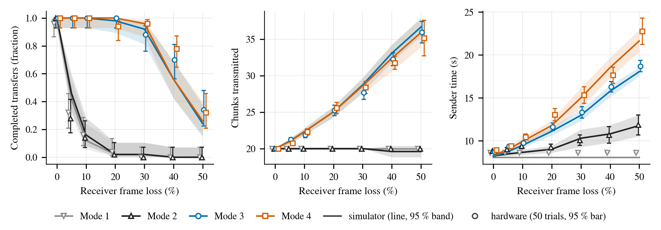
To verify that firmware timing and state transitions match the simulator, the two Heltec nodes of Section III-F were driven by a host script across 50 trials per mode at SF7 for \(p \in \{0,5,10,20,30,40,50\}\%\) emulated receiver frame loss (and 5 trials at SF10 for \(p \in \{0,20,40\}\%\), repeating handshakes up to 6 times). Table VII and Fig. 7 compare hardware against 50 simulation seeds. Across all evaluated points, 95% confidence intervals for completion fraction, transmitted chunks, and sender time overlap consistently. Reliable modes (Modes 3 and 4) maintain over 94% delivery up to 20% loss and over 88% at 30% loss. Measured hardware sender time is on average 5% (SF7) and 3% (SF10) above simulated values due to microcontroller SPI overhead and FreeRTOS task scheduling jitter.
| Frame loss | Mode 1 | Mode 3 | Mode 4 |
| 0% | 0.96 / 1.00 | 1.00 / 1.00 | 1.00 / 1.00 |
| 5% | 0.32 / 0.42 | 1.00 / 1.00 | 1.00 / 1.00 |
| 10% | 0.16 / 0.12 | 1.00 / 1.00 | 1.00 / 1.00 |
| 20% | 0.04 / 0.02 | 1.00 / 0.98 | 0.94 / 1.00 |
| 30% | 0.00 / 0.02 | 0.88 / 0.92 | 0.96 / 0.96 |
| 40% | 0.00 / 0.00 | 0.70 / 0.56 | 0.78 / 0.56 |
| 50% | 0.00 / 0.00 | 0.34 / 0.24 | 0.32 / 0.26 |
This laboratory bench evaluates protocol logic and timers under emulated i.i.d. loss over a high-margin link, rather than RF propagation or hardware sensitivity. Pre-campaign testing identified and corrected session pruning race conditions and burst-scaled SACK timeouts before the reported sweeps.
This paper presented LAMP, a lightweight transport architecture for transmitting large segmented payloads over raw LoRa. By combining cumulative bitmask SACK-ARQ with implicit frame boundary derivation, LAMP raises goodput by 14–16% at SF7, extends 90% PDR delivery range by 22–35% in urban environments, and eliminates per-packet acknowledgment airtime.
Protocol Scope and Limitations: Five architectural boundaries are identified: (i) Capacity: Single sessions are bounded to 255 chunks \(\times \) 244 B \(\approx 62.2\) kB (larger transfers require application chunking); (ii) Memory: Incomplete sessions hold \(N\,(S_{\mathrm {pkt}}+S_{\mathrm {node}})\) bytes (5.74 kB for \(N=20\)) plus \(N\,S_{\max }\) upon completion; (iii) Security: Frame integrity relies on CRC-16 without nonces; (iv) Synchronous Path: Transmit calls block while awaiting SACK feedback; and (v) Evaluation: Fading models are empirical published fits, and the bench emulates i.i.d. frame loss over a laboratory link.
Architectural Roadmap and Future Work: We outline a three-level architectural roadmap and future work: (i) Level 1 – Addressed Transport (Current): 8-bit addressing, 9-byte header, four operational modes, and dynamic 3WHS; (ii) Level 2 – Spectrum Access, Rates & Security (Near-Term): CAD/CSMA-CA backoff under ETSI EN 300 220-1 [6], dynamic ADR via SACK feedback, TDMA channel access [23], and AES-128-GCM; (iii) Level 3 – Multi-Hop Mesh & IPv6 Extension (Long-Term): Dynamic multi-hop routing (AODV-Light / RPL adaptation) with hop-by-hop vs. end-to-end SACK [24, 25, 16] and IPv6 link-local bridging (fe80::/64); and (iv) Future Work: Outdoor field campaigns (sweeping 1 to 5000 m in LoS/NLoS) are planned to characterize shadow fading, calibrate hardware sensitivity offsets, and validate multi-node coexistence [12].
Declarations: Source code, HAL drivers, tests, bench firmware, ns-3 models, and datasets are at https://github.com/aleemont1/lmp (MIT license). No human/animal subjects were involved. AI tools assisted strictly in formatting and style calibration per IEEE guidelines. The author declares no competing interests.
[1] M. Radeta, J. Pestana, P. Abreu, R. Freitas, F. Silva, D. Vieira, R. Prieto, M. Fernandez, F. Alves, T. Dellinger, S. Neves, and E. Delory, “TRITON—open telemetry and location estimation for marine monitoring based on IoT and LoRa,” IEEE Journal of Oceanic Engineering, vol. 50, no. 2, pp. 1244–1258, 2025.
[2] D. Croce, M. Gucciardo, S. Mangione, G. Santaromita, and I. Tinnirello, “LoRa technology demystified: From link behavior to cell-level performance,” IEEE Transactions on Wireless Communications, vol. 19, no. 2, pp. 822–834, 2020.
[3] F. Adelantado, X. Vilajosana, P. Tuset-Peiro, B. Martinez, J. Melia-Segui, and T. Watteyne, “Understanding the limits of LoRaWAN implementations,” IEEE Communications Magazine, vol. 55, no. 9, pp. 34–40, 2017.
[4] S. De, H. M. Jalajamony, S. Adhinarayanan, S. Joshi, H. Upadhyay, and R. Fernandez, “Multimedia transmission over LoRa networks for IoT applications: A survey of strategies, deployments, and open challenges,” Sensors, vol. 25, no. 23, p. 7128, 2025.
[5] P. J. Marcelis, V. S. Rao, and R. V. Prasad, “DaRe: Data recovery through application layer coding for LoRaWAN,” in Proceedings of the 2017 IEEE/ACM Second International Conference on Internet-of-Things Design and Implementation (IoTDI), 2017, pp. 97–108.
[6] Short Range Devices (SRD) operating in the frequency range 25 MHz to 1 000 MHz; Part 1: Technical characteristics and methods of measurement, European Telecommunications Standards Institute (ETSI) Std. ETSI EN 300 220-1 V3.1.1, 2017.
[7] O. Gimenez and I. Petrov, “Static context header compression (SCHC) over LoRaWAN,” Internet Engineering Task Force (IETF), RFC 9011, April 2021.
[8] T. Chen, D. Eager, and D. Makaroff, “Efficient image transmission using LoRa technology in agricultural monitoring IoT systems,” in 2019 IEEE International Conference on Internet of Things (iThings) and IEEE Green Computing and Communications (GreenCom) and IEEE Cyber, Physical and Social Computing (CPSCom) and IEEE Smart Data (SmartData), 2019, pp. 937–944.
[9] A. Minaburo, L. Toutain, C. Gomez, D. Barthel, and J. C. Zúñiga, “SCHC: Generic framework for static context header compression and fragmentation,” Internet Engineering Task Force (IETF), RFC 8724, April 2020.
[10] LoRa Alliance Technical Committee, “LoRaWAN fragmented data block transport specification,” LoRa Alliance, Technical Specification TS004-2.0.0, 2022.
[11] P. Thubert, “IPv6 over low-power wireless personal area network (6LoWPAN) selective fragment recovery,” Internet Engineering Task Force (IETF), RFC 8931, November 2020.
[12] M. Cattani, C. A. Boano, and K. Römer, “An experimental evaluation of the reliability of LoRa long-range low-power wireless communication,” Journal of Sensor and Actuator Networks, vol. 6, no. 2, p. 7, 2017.
[13] M. Bor, U. Roedig, T. Voigt, and J. M. Alonso, “Do LoRa low-power wide-area networks scale?” in Proceedings of the 19th ACM International Conference on Modeling, Analysis and Simulation of Wireless and Mobile Systems (MSWiM), 2016, pp. 59–66.
[14] M. McCauley, “RadioHead packet radio library for embedded microprocessors,” https://www.airspayce.com/mikem/arduino/RadioHead/, accessed: Sep. 2026.
[15] J. M. Solé, R. P. Centelles, F. Freitag, and R. Meseguer, “Implementation of a LoRa mesh library,” IEEE Access, vol. 10, pp. 113 158–113 171, 2022.
[16] J. M. Solé, R. Pueyo Centelles, F. Freitag, R. Meseguer, and R. Baig Viñas, “Large and reliable data transfer service for LoRa mesh network applications,” Computer Communications, vol. 248, p. 108404, 2026.
[17] M. Mathis, J. Mahdavi, S. Floyd, and A. Romanow, “TCP selective acknowledgment options,” Internet Engineering Task Force (IETF), RFC 2018, October 1996.
[18] A. Calabrò, E. Marchetti, and M. T. Paratore, “Evaluating use of ARQ strategies in communication protocols for search and rescue,” in Proceedings of the 21st International Conference on Web Information Systems and Technologies (WEBIST). SCITEPRESS, 2025, pp. 59–70.
[19] Semtech Corporation, “SX1272/3/6/7/8: LoRa modem designer’s guide,” Semtech Corporation, Tech. Rep. Application Note AN1200.13, Rev. 1, July 2013.
[20] J. Petäjäjärvi, K. Mikhaylov, A. Roivainen, T. Hänninen, and M. Pettissalo, “On the coverage of LPWANs: range evaluation and channel attenuation model for LoRa technology,” in 2015 14th International Conference on ITS Telecommunications (ITST), 2015, pp. 55–59.
[21] M. Rademacher, H. Linka, T. Horstmann, and M. Henze, “Path loss in urban LoRa networks: A large-scale measurement study,” in 2021 IEEE 94th Vehicular Technology Conference (VTC2021-Fall), 2021, arXiv:2109.07768.
[22] J. A. Azevedo and F. Mendonça, “A critical review of the propagation models employed in LoRa systems,” Sensors, vol. 24, no. 12, p. 3877, 2024.
[23] C.-C. Wei, J.-K. Huang, C.-C. Chang, and K.-C. Chang, “The development of LoRa image transmission based on time division multiplexing,” in 2020 International Symposium on Computer, Consumer and Control (IS3C), 2020, pp. 323–326.
[24] J. Kim, J. Jenkins, J. Seol, and M. Kwak, “Extending data transmission in the multi-hop LoRa network,” Issues in Information Systems, vol. 23, no. 3, pp. 292–304, 2022.
[25] A. W.-L. Wong, S. L. Goh, M. K. Hasan, and S. Fattah, “Multi-hop and mesh for LoRa networks: Recent advancements, issues, and recommended applications,” ACM Computing Surveys, vol. 56, no. 6, pp. 1–43, 2024.